MP2: Terrain Modeling
Due: March. 4, 2022 @ 11:59 PM
Important Notes
Table of Contents
- Terrain Generation
- The Faulting Method
- Faulting Method Overview
- Implementation
- Implement the method
generateTriangles()in Terrain.js - Implement the methods
getVertex(v,i)andsetVertex(v,i)in Terrain.js - Implement the method
shapeTerrain()in Terrain.js - Use
gl.drawElementsin Terrain.js - Complete
calculateNormals()in Terrain.js - Implement a perspective view in MP2.js
- Implement the Phong reflection model and Phong shading
- Implement an elevation-based colormap for the terrain
- Implement the method
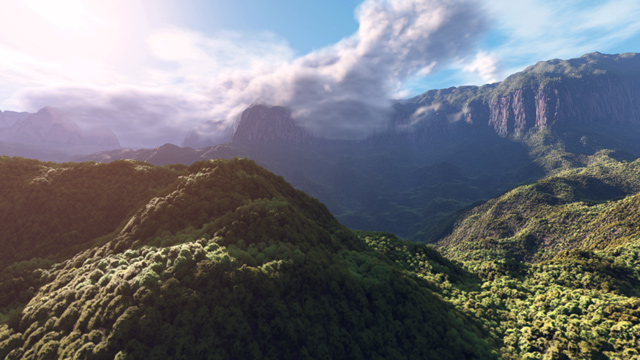
For your second Machine Problem, you will procedurally model a piece of terrain.
- The terrain will be finite…do not be concerned about being able to see the boundary.
- The scene will be static…meaning you will not interactively change your view of it/
- We will add interaction in a following MP, so write good code that you can reuse.
Terrain Generation
Many basic terrain modeling algorithms employ something called Perlin noise to create a highly detailed natural appearance. Invented by Ken Perlin in 1982 while working on the movie Tron, Perlin noise uses randomness and repetition to synthesize 2D and 3D textures. In 1997, Perlin won an Academy Award for Technical Achievement from the Academy of Motion Picture Arts and Sciences for this contribution to graphics. Perlin noise and techniques based off of it are still widely used in games and movies today.
Realistic terrain generation in modern games require tools that do more than just model the basic underlying terrain…these tools support operations like creation of vegetation and roads and erosion. See this talk by Ubisoft developer Etienne Carrier if you are interested in seeing the tools technical artists use these days.
The Faulting Method
For this MP we will write code to generate a basic 3D terrain. We won’t be using Perlin’s function…instead we will do something conceptually similar but less efficient…but easier to implement. This method is called the faulting method and was initially proposed by Benoit Mandelbrot in 1982.
You can find a summary of the faulting method in section 3.1.2 of the following survey paper on terrain generation algorithms:
A Review of Digital Terrain Modeling. Eric Galin, Eric Guérin, Adrien Peytavie, et al. [PDF]
Faulting Method Overview
The first step in our implementation will be to create a flat, triangulated surface in which all the vertices have \(z\) coordinates of \(0\).
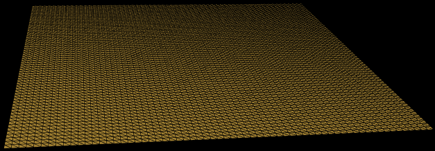
In the above image, the view is generated by using a view transformation based on a matrix generated by a call to glmatrix.mat4.lookAt(out, eye, center, up) that has us looking down onto the \(z=0\) plane.
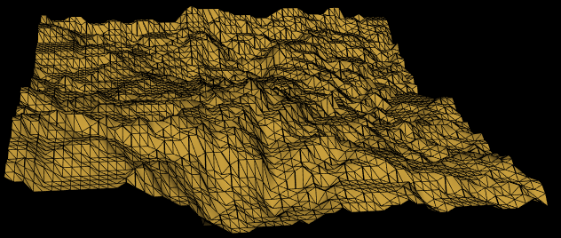
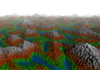
After that we will repeatedly, randomly generate an imaginary fault plane cutting through the terrain that partitions the vertices. On one side of the plane we will increase the height of each vertex by some amount \(\Delta\). On the other side, we decrease the vertex heights by \(\Delta\). After enough iterations, you should see something resembling a 3D terrain.
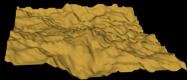
Here it is without the triangle boundaries, shaded using the Phong reflectance model.
Implementation
You can use the following starter code:
Your tasks are the following:
Implement the method generateTriangles() in Terrain.js
We will generate a mesh using an indexed face representation. This means we will have one block of data that specifies the positions of the vertices and another block of data that specifies the connectivity of the triangles. This function fills in an array called positionData which contains the \(x,y,z\) coordinates of each vertex. Theses positions can be generated in the following manner:
    var deltaX=(this.maxX-this.minX)/this.div;
    var deltaY=(this.maxY-this.minY)/this.div;

    for(var i=0;i<=this.div;i++)
       for(var j=0;j<=this.div;j++)
       {
           this.positionData.push(this.minX+deltaX*j);
           this.positionData.push(this.minY+deltaY*i);
           this.positionData.push(0);
       }
The function also will generate the triangles for the mesh by filling faceData. Each face will represented by a triple \(v_i,v_j,v_k\) of integers which are the indices of the vertices at the triangle corners. For example \(0,1,10\) would mean the triangle is formed by vertex 0, 1, and 10 in positionData. SInce positionData is actually a 1D array of floats, with each vertex requiring 3 floats, the start of the coordinates for the vertices will be at index 0, index 3, and index 30 in positionData.
To generate the faceData imagine the vertices as a 2d grid of points. Each rectangle of the grid can be formed by two triangles. The indices of the vertices at the corner of a triangle are determined by their order of insertion in the above code. For example, the triangles in the lower left corner of the grid will be \(0,1,T+1\) and \(1,T+2,T+1\) where \(T\) is the number of triangles along the \(x\)-axis. Note these triangles must have their vertices specified in counter-clockwise (CCW) order for normal vectors to be generated in the correct direction.
Implement the methods getVertex(v,i) and setVertex(v,i) in Terrain.js
These methods are accessor and mutator methods to help make working with the positonData syntactically simpler. It allows you to use a single function call to work with the \(x,y,z\) coordinates of a vertex by abstracting the implementation of positionData as a flat array of floats. Here is an exampled implementation of getVertex
/**
     * Returns the x,y,z coords of the ith vertex.
     * @param {Object} v An array of length 3 to hold the x,y,z coordinates.
     * @param {number} i The index of the vertex to get.
     */
    getVertex(v, i) {
        v[0]=this.positionData[i*3];
        v[1]=this.positionData[i*3 + 1];
        v[2]=this.positionData[i*3 + 2];
    }
Implement the method shapeTerrain() in Terrain.js
The rectangle for your surface mesh should have corners \((x_{min},y_{min},0)\) and \((x_{max},y_{max},0)\). To implement the faulting method you need to:
Construct a Random Fault Plane
We will construct a fault plane cutting through the terrain by generating a random point \(p\) and random direction vector \(\vec{n}\) to define the plane.
- First generate a random point \(p\) in the rectangle \((x_{min},y_{min},0) \times (x_{max},y_{max},0)\).
- Generate a random normal vector \(\vec{n}\) for the plane \(<x_n,y_n,0>\), where \(x_n,y_n\) is a point uniformly sampled on the unit circle.
You can easily generate a random vector using
glMatrix.vec2.random(out)Alternatively, if \(\theta\) is a random angle in \([0,2\pi]\) then an appropriate random normal would be \(\vec{n}=(\cos{\theta},\sin{\theta},0)\).
Raise and Lower Vertices
Iterate over the vertices and do the following:
- Given a vertex \(b\), test which side of the plane that vertex falls on by using the dot product test \((b-p) \cdot n \ge 0\).
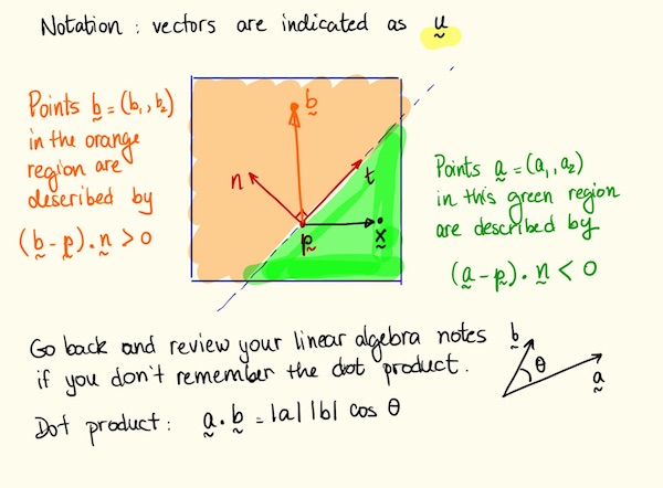
- If \(b\) is in the negative half-space, lower the \(z\) coordinate of by some amount \(\Delta\).
- If \(b\) is in the positive half-space, raise the \(z\) coordinate of by some amount \(\Delta\).
Optional You may get better results with disatnce weighted diplacements for \(\Delta\). To do so compute the distance \(r=\mathbf{d}(b,\Phi_i)\) from \(b\) to the fault plane \(\Phi_i\) and alter the \(\Delta\) you use for each vertex by a coefficient function \(g(r)=(1-(r/R)^2)^2\) for \(r<R\) and \(g(r)=0\) elsewhere. \(R\) is a parameter you determine.
- Make multiple passes over the vertices generating faults and altering vertex heights until you have a good result.
Important Let \(\Delta_i\) be the faulting parameter in pass \(i\) over the vertices. Next pass use \(\Delta_{i+1} = \frac{\Delta_i}{2^H}\) where \(H\in[0,1]\)
Parameters
You will need to experiment with the parameters of algorithm to find ones that give good results. The images above used 100 iterations of partitioning on a \(64 \times 64\) grid of vertices spanning a unit square with \(\Delta = 0.005\) and \(H=\)0. You should use a larger value for \(H\).
Use gl.drawElements in Terrain.js
Your implementation should generate an indexed mesh and render it using the WebGL function void gl.drawElements(mode, count, type,offset) The starter code does this, but you should pay attention to the type parameter as the type gl.UNSIGNED_SHORT will limit your mesh to having only 65536 vertices. If you want more, you will need to use the gl.UNSIGNED_INT.
Complete calculateNormals() in Terrain.js
In order for the mesh to be shaded correctly you will also need to generate per-vertex normals for the mesh. Each normal is a vector perpendicular to the mesh at the vertex, and should be computed as a triangle area-weighted average of the normals of the triangles that surround the vertex. These normals will be another attribute that you will need to send down to the vertex shader.
Generating per-vertex normals is discussed in the Feb 11 Lecture available at this Link.
Implement a perspective view in MP2.js
Your code should generate a view matrix and a perspective projection matrix in the JS portion of the app and send them to the vertex shader…and use them to transform the vertices. You should use the glMatrix library functions lookAt(out, eye, center, up) and perspective(out, fovy, aspect, near, far) to generate the matrices. It is up to you to understand how to specify the parameters to generate a good view.
Implement the Phong reflection model and Phong shading
Implement the Phong illumination model with Phong shading. This means your shading calculations should be done per-fragment..meaning in the fragment shader. You can position your light source(s) anywhere in the scene as long as the rendered images are well-lit.
The starter code implements the Phong reflection model with Gouraud shading. In order to move the computation to the fragment shader you will need to do the following:
- Send an interpolated normal vector from the vertex shader to the fragment shader. Normalize this vector in the fragment shader.
- Send an interpolated position value from vertex shader to the fragment shader.
- Calculate the reflection vector in the fragment shader instead of the vertex shader.
- Send the light position and colors to the fragment shader from your JS code as
uniformvariables.
For this MP you will generate material colors in the vertex shader…you will need to generate a color for the terrain based on elevation as described below. You can set the shininess coefficient \(\alpha\) however you wish (e.g. \(\alpha=1\) for all shading computations is acceptable ).
Implement an elevation-based colormap for the terrain
In your shading calculation, you should assign material colors (the \(k\) values in the Phong model) to vertices based on the elevation of the vertex. If you use the \(z\)-coordinate as elevation, that means you should base your color assignment on the value of the \(z\)-coordinate. For example, you could define four different intervals of z values and assign blue to the vertices in the lowest interval, green to the second lowest, brown to the second highest, and white to the highest. You should define your own color scheme…you can be creative and do not need to mimic the picture shown here.
To make the calculation simpler, you should implement the following:
-
In Terrain.js, implement methods
getMaxElevation()andgetMinElevation()that return the max and min \(z\) coordinate in the terrain. -
Send these values to the vertex shader as
uniformvariables. -
In the vertex shader, compute a normalized elevation for the vertex using code like this:
in vec3 vertexPosition; uniform float minZ; uniform float maxZ; void main(void) { float nrmZ; nrmZ = vertexPosition.z-minZ/(maxZ-minZ); .... } -
Then, you can set the values of
kAmbientandkDiffuseusing a colormap based onnrmZknowing thatnrmZ\(\in [0,1]\)
Note that kAmbient and kDiffuse must be local variables in the shader, they cannot be declared as uniform variables in the shader since you are assigning values to them in the shader code.
You can keep kSpecular = vec4(1,1,1,1) for this MP.
After assigning the material colors in the vertex shader, pass them as varyings using out in vertex shader to send the colors to an in variables in the fragment shader to complete the shading process.
Debugging Tips
- Start by generating a small flat terrain (for example 3 vertices by 3 vertices). Use this to set up the view you want.
- Then, add in the ability to set the z coordinates of the vertices. Do something simple like random heights.
- Then, work on implementing the terrain generation algorithm.
- Use the newest version of the glMatrix library
Submission Instructions
Submit all the files needed to run your app including gl-matrix-min.js or similar library files
Submit the files in zipped folder to Canvas.
Use the following naming conventions for your files:
-
mpN.html
-
mpN.js
-
You can use any naming convention you wish for additional JS you use (e.g. Terrain.js or Sphere.js, etc.)
Test your app right before you submit and after renaming any files.
Not updating the name of a JS file file sourced in mpN.html is a common bug
In the file name, replace N with the number of the MP (e.g. MP1.html).
You should also include any additional files you use or have written.
In particular you can use the glMatrix library gl-matrix-min.js.
Name your submission as NETID_MPN.zip and submit it to Canvas, where NETID is your netid and N is the MP number. This MP (as are the other MP’s) is more than just an assignment for a grade to verify graphics programming proficiency. It is also an opportunity to impress me, your friends/family and your future employer or graduate school.
| Name | Points | Description |
|---|---|---|
| Runs and renders | 10 | Program runs without crashing and renders visible polygons. |
| Commented | 10 | Each function in your code is commented in the required style. |
| Normals | 20 | Normal vectors for the terrain are computed and handled correctly. |
| Terrain Generation | 20 | The terrain is modeled using the random partition method. |
| Elevation Color Map | 20 | The shading of the terrain changes by mapping different ranges of elevation to different colors. |
| Phong Shading | 10 | Shading model computation is in the fragment shader. |
| Creativity | 10 | The color map is visually interesting and the terrain exhibits good aesthetic quality (e.g. not totally random). |
| Total | 100 |